
Step into a ship’s engine room, and you are met with the deep, rhythmic roar of the main engine—the very pulse of the vessel’s power. Within the multi-cylinder diesel engine, a dozen or more cylinders fire in a precise, alternating sequence. Beneath what might sound like a chaotic din lies a strictly defined operational order: the engine’s “firing order.” Far from being an arbitrary numerical sequence chosen by the manufacturer, this firing order is a finely tuned set of mechanical rules—shaped by crankshaft dynamics, overall engine balance, and thermal load management—that serves as a vital reference for engine room personnel when troubleshooting faults or assessing the engine’s operating condition.
I. What is the firing order of a diesel engine?
The “firing order” of a marine diesel engine refers to the sequence in which the cylinders of a multi-cylinder engine reach top dead center (TDC) on the compression stroke—at predetermined crankshaft angle intervals—to undergo fuel injection, combustion, and the subsequent transmission of force to drive the rotation of the crankshaft.
In principle, a diesel engine relies on the force generated by the combustion of fuel within the cylinder to drive the piston downward; this motion is then converted into rotational torque at the crankshaft via the connecting rod. While a single-cylinder engine produces intermittent torque, a multi-cylinder engine utilizes staggered firing intervals, ensuring that at least one cylinder is performing work at any given point in the crankshaft’s rotation, thereby delivering smooth power output. The firing order is essentially the result of a precise coordination between the crankshaft’s crank-throw angles, fuel injection timing, and valve timing; it directly influences the forces exerted on the crankshaft, the vibration characteristics of the engine, and its overall operational reliability.
The basis for determining firing intervals varies according to the engine’s operating cycle:
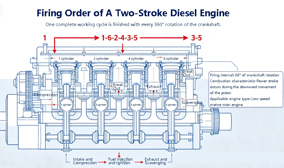
• Two-stroke low-speed main engine: One complete operating cycle is finished for every 360° rotation of the crankshaft, with a single firing event per cylinder; the theoretical firing interval angle is 360° divided by the number of cylinders.
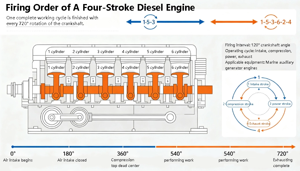
• Four-stroke medium-to-high-speed auxiliary engine: One complete operating cycle occurs every 720° of crankshaft rotation, with each cylinder firing once; the theoretical firing interval angle is 720° divided by the number of cylinders.
II. Core Principles for Designing the Firing Sequence
Marine diesel engines often boast thousands of horsepower; if the firing order is poorly designed, the consequences can range from excessive vibration and accelerated component wear to more severe issues, such as fatigue-induced crankshaft fracture or cracking of the engine block. In the industry, the design of firing orders consistently adheres to four core principles:
1. Uniform and Continuous Torque Output
The firing intervals between cylinders must be strictly equal to ensure a stable power input to the crankshaft throughout its entire rotation, thereby avoiding any “torque gaps.” For instance, in a 6-cylinder, four-stroke auxiliary engine, the firing interval is fixed at 120° of crankshaft rotation; a cylinder fires every 120°, resulting in a torque output with virtually no fluctuation. This is the fundamental basis for the ability of auxiliary engines in marine power plants to provide a stable power supply.
3. Force Balance of the Crankshaft and the Engine Assembly
The firing order must be coordinated with the angular arrangement of the crankshaft throws to ensure that reciprocating and centrifugal inertial forces cancel each other out as much as possible. In the case of V-type diesel engines, the firing sequence is specifically designed so that the cylinders in the two banks fire alternately; this helps counteract the lateral forces resulting from the V-angle, thereby reducing both the lateral and longitudinal vibrations of the engine assembly.
2. Avoiding Consecutive Firing of Adjacent Cylinders
If cylinders 1, 2, and 3 were to fire in immediate succession, the resulting impact forces would concentrate at the front end of the crankshaft. This would cause a sharp, localized increase in bending moment and lead to cumulative engine vibration. Consequently, well-engineered firing orders are designed to ensure that adjacent cylinders do not fire consecutively. This distributes the forces across different sections of the crankshaft, thereby reducing the load on the main bearings and extending the service life of both the crankshaft and the bearing shells.
4. Reducing Thermal Load and Exhaust Interference
Sequential firing of adjacent cylinders leads to mutual interference of gas flows within the exhaust passages, which impairs scavenging efficiency. Furthermore, it causes an accumulation of thermal load on adjacent cylinder liners and pistons, increasing the risk of overheating and thermal erosion. An appropriate firing order ensures a more uniform distribution of thermal load across the cylinders, while simultaneously optimizing exhaust pulse energy to enhance the operating efficiency of the turbocharger.
III. Typical Firing Orders for Mainstream Marine Diesel Engines
Marine diesel engines are categorized into two main groups: low-speed two-stroke main engines and medium- to high-speed four-stroke auxiliary engines. Each mainstream engine model follows established conventions for its firing order—a fundamental piece of operational knowledge that engine room personnel must commit to memory.
1. Low-speed two-stroke main engines (MAN B&W and WinGD series)
Low-speed engines serve as the primary propulsion power for ships. In-line configurations with 6, 7, or 8 cylinders are the most common, while some large container ships utilize V-type engines with 10 to 14 cylinders.
• 6-cylinder in-line two-stroke: A typical firing order is 1-6-2-4-3-5, with a firing interval of 60° of crankshaft rotation; this is the classic configuration for the MAN 6S series of main engines.
• 7-cylinder in-line two-stroke: The firing interval is approximately 51.4°, with a typical firing order of 1-3-5-7-2-4-6; this is commonly found in models such as the MAN 7S60ME-C.
• 8-cylinder in-line two-stroke: A typical firing order is 1-8-4-2-7-3-5-6, which balances the forces on the crankshaft by alternating the firing sequence between the ends of the engine.
For V-type low-speed engines, an “alternating firing between the left and right banks” strategy is generally employed. For instance, in a V12 engine, the firing sequence alternates—cylinder 1 on the left bank, cylinder 2 on the right bank, cylinder 3 on the left bank, cylinder 4 on the right bank, and so on—ensuring that the forces acting on both sides of the V-angle remain symmetrical.
2. Medium- to high-speed four-stroke auxiliary engines (e.g., Yanmar, Wärtsilä, Cummins, etc.)
Marine auxiliary engines used for power generation are predominantly four-stroke, inline 4-cylinder or 6-cylinder units, with firing orders that are highly standardized across the industry.
• In-line 4-cylinder, four-stroke: The most common firing order is 1-3-4-2, with a firing interval of 180°. This configuration is frequently used for low-power emergency generator sets.
• In-line 6-cylinder, four-stroke: The industry-standard firing order is 1-5-3-6-2-4, with a firing interval of 120°. This design is employed in mainstream marine auxiliary engines—such as the Yanmar 6EY18 and 6N18—and is the configuration most familiar to engine room personnel.
• V-type 8-cylinder / 12-cylinder, four-stroke: These engines utilize an alternating firing sequence between the left and right cylinder banks. For instance, a common firing order for a V8 engine is 1-8-4-3-6-5-2-7, which ensures optimal vibration characteristics and torque output for the engine as a whole.
IV. Hazards and Typical Faults Resulting from Incorrect Firing Order
The firing order serves as the “metronome” for a diesel engine’s operation. Any disruption to this sequence—whether caused by the incorrect installation of timing gears, misalignment in the fuel injection pump drive, or deviations in camshaft positioning—will inevitably trigger a series of severe malfunctions. On one particular vessel, a timing gear was found to be misaligned by a single tooth following maintenance. While the main engine could operate at low loads, increasing the output to a typical operational load—the level used during sea voyages—resulted in intense, engine-wide vibration, uneven exhaust temperatures, and intermittent surging of the turbocharger. The issue was only resolved after the firing timing was re-calibrated.
Specifically, an incorrect firing order can lead to four main types of adverse consequences:
1. Severe torque fluctuations: Unstable rotational speeds and significant load variations can, in extreme cases, trigger torsional resonance in the crankshaft or even lead to an engine overspeed (runaway) event.
3. Abnormal combustion and exhaust: Issues such as exhaust backfire or “popping” within the cylinders can occur; airflow turbulence at the turbocharger intake may trigger surging, while poor scavenging in certain cylinders can lead to significant carbon buildup.
2. Thermal load imbalance: Cylinders with consecutive firing sequences become overheated, which significantly accelerates the ablation (erosion/burning away) of pistons, cylinder liners, and exhaust valves.
4. Damage to the crankshaft and bearings: Concentrated, repetitive impact forces exerted on specific main bearings can rapidly cause scoring of the bearing shells and delamination of the alloy layer; long-term operation may result in fatigue cracking of the crankshaft.
V. How Engine Room Personnel Can Effectively Utilize the Firing Order
The firing order is not merely a design parameter; it is also a practical tool for engine room operation and maintenance. Proficient application of the firing order can significantly enhance the efficiency of troubleshooting and operational management.
1. Single-Cylinder Fault Localization
When performing a single-cylinder fuel-cutout test, cut off the fuel supply to each cylinder sequentially—following the firing order—while observing the drop in engine speed and changes in vibration. If the speed drop for a particular cylinder is significantly smaller than that of the others, it can generally be concluded that the cylinder is underperforming or experiencing poor combustion. Using a peak-pressure gauge in conjunction with this test allows for the rapid identification of the faulty cylinder.
2. Troubleshooting Abnormal Noises and Vibrations
When a periodic abnormal noise occurs in the main engine, the scope of the fault can be narrowed down by analyzing the relationship between the frequency of the noise and the firing interval. For instance, an impact sound occurring every 120° of crankshaft rotation in a 6-cylinder, four-stroke engine—when cross-referenced with the firing order—can help quickly determine whether the issue is piston slap, bearing looseness, or valve impact.
3. Planning for Cylinder Overhauls
When overhauling multiple cylinders, avoid dismantling cylinders that fire in immediate succession. This ensures that the remaining operational cylinders maintain an even firing interval, preventing excessive vibration during any interim periods of operation. For example, when overhauling a 6-cylinder engine, one might first dismantle cylinders 1, 3, and 5, followed by 2, 4, and 6, thereby maintaining a balanced load on the crankshaft.
4. Balancing Operational Conditions
During routine measurements of peak cylinder pressure and exhaust temperature, recording and comparing the data according to the firing order provides a clear view of the uniformity of power output. If the exhaust temperatures for several consecutively firing cylinders are consistently high, it may indicate interference within the exhaust system or a systemic shift in fuel injection timing.
5. Valve Clearance Verification
For four-stroke diesel engines, valve clearances must be measured and adjusted only when the valves are fully closed and the cams are positioned on their base circles. Since the firing order dictates the sequence in which each cylinder reaches its compression top dead center (TDC), it serves as a crucial reference for marine engineers to efficiently perform valve clearance checks—a process particularly essential for the routine maintenance of auxiliary engines and for reassembly following a cylinder overhaul.
(1) Cylinder-by-Cylinder Adjustment Method: Calibrating each cylinder in the order of the firing sequence.
The cylinder-by-cylinder method offers the highest precision and is the standard procedure following the overhaul of marine auxiliary engines (specifically after “pulling” the cylinders). Taking a 6-cylinder, four-stroke auxiliary engine with a firing order of 1-5-3-6-2-4 as an example, the operational logic is as follows:
1. Rotate the crankshaft in its normal direction of operation until the piston of the first cylinder reaches top dead center (TDC) on the compression stroke. (This can be verified by cross-referencing the markings on the flywheel with the positions of the valve stems.) At this point, both the intake and exhaust valves for that cylinder are fully closed, allowing for the adjustment of both valve clearances.
2. Following the firing order, rotate the crankshaft by 120° (the theoretical firing interval) to bring the next cylinder to TDC on its compression stroke. Proceed in this manner to adjust the valve clearances for cylinders 5, 3, 6, 2, and 4, in sequence.
This method aligns perfectly with the firing sequence, minimizes measurement error, and is well-suited for overhauling engines that require high precision in valve timing.
(2) Two-Stage Adjustment Method: The “Both, Exhaust, Neither, Intake” Rule (based on the firing order).
For routine, rapid checks, marine engineers often employ a “two-stage” method to adjust all valve clearances. The core logic relies on the firing sequence to determine the operational state of each cylinder. Again, using a 6-cylinder, four-stroke engine (firing order 1-5-3-6-2-4) as an example:
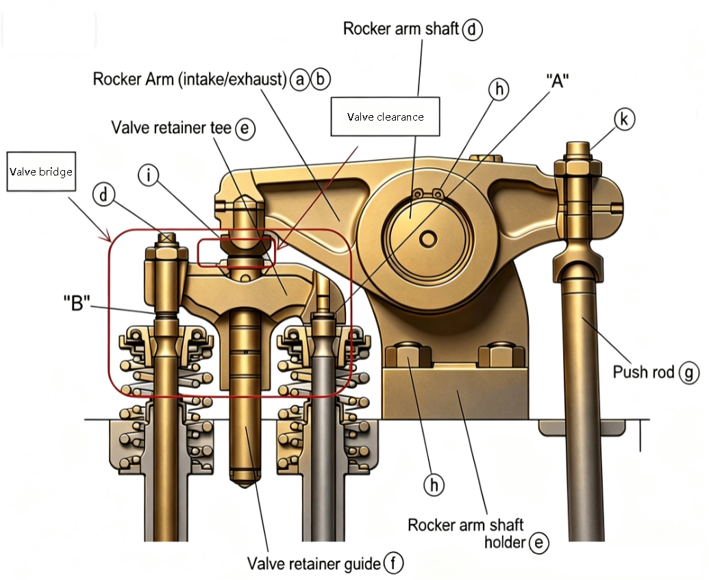
• When cylinder 1 is at TDC on the compression stroke, apply the “Both, Exhaust, Neither, Intake” rule: for cylinder 1, both intake and exhaust valves can be adjusted (“Both”); for cylinders 3 and 5, only the exhaust valves can be adjusted (“Exhaust”); for cylinder 6, neither valve can be adjusted (“Neither”); and for cylinders 2 and 4, only the intake valves can be adjusted (“Intake”). • After completing the aforementioned adjustments, rotate the crankshaft 360° to bring cylinder 6 to the top dead center (TDC) of the compression stroke. Then, adjust all remaining valves that have not yet been set (both intake and exhaust valves for cylinder 6; exhaust valves for cylinders 2 and 4; and intake valves for cylinders 3 and 5). By following this two-step process, the valve clearances for all six cylinders can be verified and adjusted.
This method eliminates the need to repeatedly rotate the crankshaft to position each cylinder individually, significantly enhancing the efficiency of routine maintenance on auxiliary engines—a technique commonly employed by engine room personnel.
Conclusion
The seemingly simple firing order is rooted in the fundamental dynamics and thermodynamics of a diesel engine. It is both the product of rigorous simulation and optimization during the design phase and a vital key for marine engineers to interpret the operating conditions of a main engine. For engine room personnel who work closely with these engines, mastering the principles and applications of the firing order goes beyond merely learning a single parameter; it fosters a systematic understanding of how a diesel engine functions—a crucial step in the evolution of engine management from “following prescribed procedures” to “informed, judgment-based operation and maintenance.”


